
High-End Metalwork Welding: Full-Process Workmanship Standard
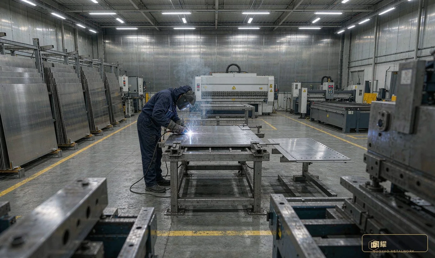
A complete process chain across three applications — luxury retail, luxury residences and luxury hotels — from detailing and sampling through to acceptance and maintenance. Core principles: factory prefabrication first · minimal site welding · sample before production · Grade A welds on every visible surface.
This guide sets out the welding workmanship standard behind high-end architectural metalwork: weld grade zoning, the ten-step process chain, base-metal and filler matching, welding parameters for stainless steel, aluminium and brass, joint preparation and groove design, distortion control, post-weld treatment and surface finishing, application-specific priorities, defect prevention and acceptance.
Materials covered: stainless steel, brass, aluminium and carbon steel. Processes: TIG, laser welding and brazing, followed by seamless grinding, PVD colour coating and anti-fingerprint treatment.
Core principles: factory prefabrication first · minimal site welding · sample before production · Grade A welds on every visible surface.
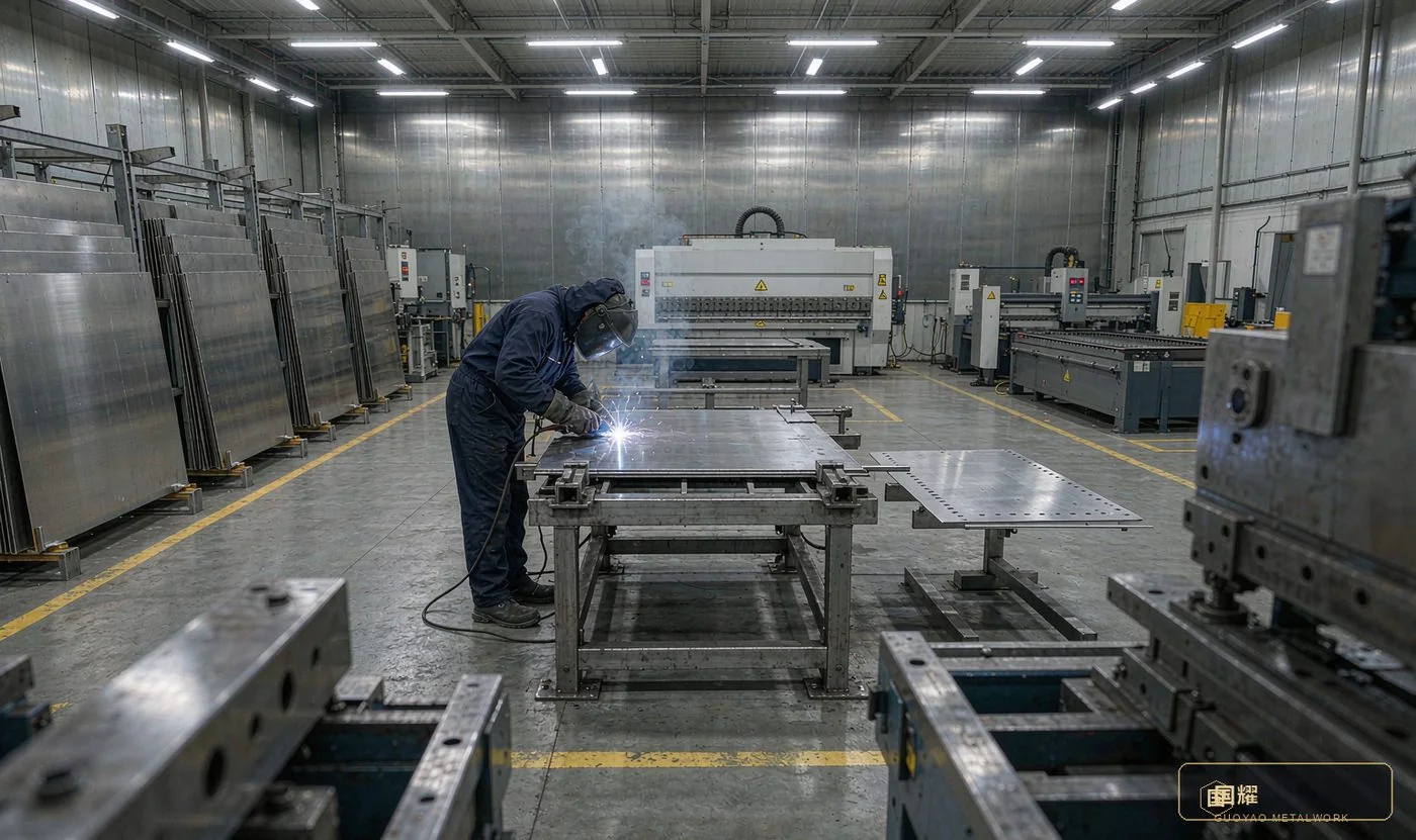
Key control targets for the whole process:
- 70% — Target factory prefabrication ratio
- ≤1mm — Flatness deviation under a 2 m straightedge
- ≤0.5mm — Permitted joint deviation, Grade A
- 3–5× — Grinding hours / welding hours
1. Set the Standard First: Weld Grades for High-End Projects
Different locations need different weld grades — fix the standard first and acceptance has a basis
In a high-end project the great majority of quality cost is spent on the visible surfaces. Before work begins, the weld grade must be confirmed with the designer, the supervisor and the client and fixed as a weld grade zoning map, making clear which surfaces must be seamless and traceless and which only have to meet strength requirements.
- Grade A — Typical locations: Luxury retail shopfronts / display cases / cash counters · Hotel lobbies, lift lobbies, primary faces of art installations · Stair handrails and screens in luxury residences · Weld appearance requirement: Weld perfectly flush with the base metal — no reinforcement, no depression, no waviness; no weld outline visible under raking light · Surface Finishing: Progressive polishing + brushed / mirror finish + PVD colour coating + anti-fingerprint · Acceptance method: Naked-eye check at 1 m plus raking light, 10× magnifier where necessary
- Grade B — Typical locations: Visible on close inspection but not a primary face · Side panels, linings, secondary passages, service bands · Weld appearance requirement: Even, continuous bead, ground smooth; no obvious undercut, porosity or weld overlap · Surface Finishing: Grinding + brushing; a very faint transition trace is allowed · Acceptance method: Visual + hand check; weld reinforcement ≤0.5 mm
- Grade C — Typical locations: Concealed structures, backing frames, embedded parts, backing stiffeners · Weld appearance requirement: Full weld, free of cracks and lack of fusion, meeting strength requirements · Surface Finishing: Slag removal + rust protection (carbon steel) / pickling and passivation (stainless steel) · Acceptance method: Structural safety inspection, with load testing where necessary
Rule of thumb: on a high-end project, the time spent grinding and polishing a Grade A weld is typically 3–5× the welding time. The number of Grade A welds should therefore be minimised at the detailing stage — anything that can be solved by folding, jointing or a concealed closure should never be left to welding.
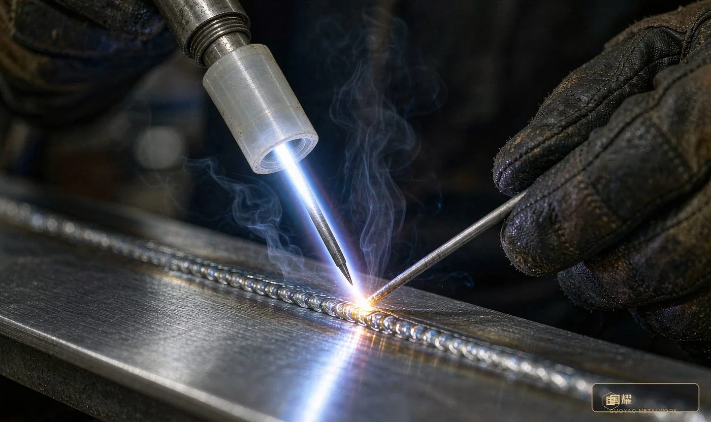
Fig. 1 — Precision TIG argon-arc welding · the preferred process for Grade A visible surfaces
Visible-surface welding on high-end projects is mainly manual TIG and laser welding: low heat input, little distortion and a narrow bead, which after progressive grinding and polishing can match the base metal for a seamless appearance.
- Heat source — A stable tungsten argon arc with a controllable molten pool, suited to 0.5–3 mm sheet and visible-surface welds
- Shielding — Argon through the cup plus argon backing; a weld free of heat tint is a precondition for Grade A acceptance
- Filler — ER308L / ER316L, φ0.8–1.0 mm, from the same batch as the base metal to control colour difference
- Objective — A narrow, uniform bead → little grinding → no waviness and no trace after polishing
Applicable standard — Grade A weld · naked-eye check at 1 m + raking light · 10× magnifier where necessary
2. The Full Process in 10 Steps
From detailing to maintenance — the input, output and key control point of every step
- STEP 01 · Detailing and site measurement — Confirm material, finish, joints and closures; re-measure the building tolerance and issue fabrication drawings
- STEP 02 · Sample approval — 1:1 mock-up to confirm radius, weld, gloss, colour difference and hand feel
- STEP 03 · Materials and consumables — Base metal from one batch, matched filler, argon purity ≥99.99%
- STEP 04 · Cutting and fit-up — Laser / waterjet cutting, deburring and degreasing, jig location and tack welding
- STEP 05 · Welding — Mainly laser or TIG: low current, fast travel, back-step sequence
- STEP 06 · Post-weld dressing — Deslag, grind and level the bead; remove pinholes and depressions
- STEP 07 · Surface Finishing — Brushed / mirror polishing → PVD colour coating → anti-fingerprint
- STEP 08 · Site installation and closure — Dry-hang / undercut anchors / cleats, expansion joints left evenly
- STEP 09 · Acceptance — Weld inspection, flatness, colour consistency and lighting check
- STEP 10 · Protection and maintenance — Protective film and corner guards; hand over the cleaning and care manual
Key Steps in Detail
① Detailing and on-site measurement
Confirm the material grade (304 / 316L / H62 brass / 6061 aluminium) and the surface finish (mirror, brushed, sandblasted, etched, titanium gold, black titanium, bronze, anti-fingerprint); re-measure the building tolerance and fix the finished level, closure method, expansion-joint positions and access-panel positions; issue detail drawings showing joint preparation, weld positions, stiffeners, undercut anchors, cleats and embedded-part specifications.
② Sample approval
Produce a 1:1 physical mock-up covering the three typical details: corner, joint and edge trim. For luxury retail, look above all at waviness under light, visible fingerprints and evenness of gaps; for hotels, look above all at the flatness of large panels, fire rating, fixing strength and colour consistency. No production cutting may start until the sample has been signed off.
③ Material and consumable preparation
Buy base metal from a single batch wherever possible to avoid batch colour difference after coating; match the filler to the base metal (same-grade wire for stainless steel, copper wire or brazing alloy for brass, aluminium-silicon wire for aluminium); argon purity ≥99.99%, with tungsten electrodes, cups, copper backing, heat-sink plates and jigs prepared in advance; degrease, de-film and clean every material once it arrives.
④ Cutting, joint preparation and fit-up
Laser or waterjet cutting gives good edge squareness and a small heat-affected zone; deburr, break sharp edges and remove oil and oxide; for sheet, either bevel the edge or leave a 0.5–1 mm gap; for plate, prepare a V or X groove according to thickness; fit up with dedicated jigs, then re-check diagonals, flatness and squareness after tack welding.
⑤ Welding execution
For stainless sheet, laser welding first and manual TIG second; use low current, fast travel, a back-step sequence and balanced (symmetrical) welding; back-purge with argon to prevent oxidation and blackening; with brass, watch for zinc evaporation and ventilate against toxic fume; before welding aluminium, remove the oxide film with a stainless steel brush.
⑥–⑦ Post-weld treatment and surface finishing
Deslag → grind → level → progressive polish → brushed or mirror → colour coating → anti-fingerprint. Titanium coating / electroplating must be carried out only after welding, grinding and polishing are fully complete, otherwise the heat destroys the coating and causes irreversible colour difference.
⑧–⑩ Installation, acceptance and maintenance
Install dry-hang fixings, undercut anchors, cleats, embedments, structural adhesive and sealant to the detail drawings; leave adequate expansion joints so thermal movement cannot bow the panels; keep closures straight, gaps even and internal/external corners consistent; once accepted, apply protective film and corner guards and hand over the care manual.
3. Base Metal / Filler Metal Matching
Choosing the wrong filler is the single biggest cause of colour difference and rust staining after coating
- Stainless steel — Common grades: 304 / 316L / 201 · Recommended process: Laser welding > manual TIG · Filler / brazing alloy: ER308L / ER316L, φ0.8–1.0 mm · Shielding gas: Ar 99.99%, 8–12 L/min · Colour-difference risk: Low (controllable with same-batch wire)
- Brass — Common grades: H62 / H65 · Recommended process: TIG (DCEN) or brazing · Filler / brazing alloy: HS221 copper wire / BAg-25 silver brazing alloy · Shielding gas: Ar, with backing protection · Colour-difference risk: High (zinc evaporation causes colour difference)
- Aluminium and its alloys — Common grades: 6061 / 6063 / 5052 · Recommended process: AC TIG / MIG · Filler / brazing alloy: ER4043 / ER5356, φ1.0–1.2 mm · Shielding gas: Ar 99.99%, 12–15 L/min · Colour-difference risk: Medium (obvious after anodising)
- Carbon steel — Common grades: Q235 / Q355 · Recommended process: MIG / MAG / MMA · Filler / brazing alloy: ER50-6 wire / J422 electrode · Shielding gas: CO₂ or 80% Ar + 20% CO₂ · Colour-difference risk: Not applicable (paint cover required)
- Titanium and its alloys — Common grades: TA2 / TC4 · Recommended process: TIG (full inert shielding required) · Filler / brazing alloy: Matching titanium wire · Shielding gas: Ar 99.999%, trailing shield · Colour-difference risk: Medium
Common mistake: welding 316L base metal with 304 wire looks fine at first, but in damp or coastal environments the weld is the first place to show pitting and rust staining; welding brass with stainless filler leaves a silvery-white weld that can never be hidden once the bronze coating is applied.
Consumables and Tool List
- Argon at ≥99.99% purity, with flowmeter and backing-gas line
- Tungsten electrodes (ceriated, φ1.6 / 2.4 mm), ceramic cups, gas lenses
- Copper and aluminium backing bars, copper heat-sink plates (the key to distortion control)
- Stainless steel wire brushes (separate ones for aluminium and for stainless — never interchange)
- Dedicated fit-up jigs, C-clamps, cleat location blocks
- Acetone / anhydrous ethanol (degreasing), lint-free cloth
- Anti-spatter compound, anti-oxidation paste (for the back face)
- Flap discs, sanding discs, polishing wheels, brushing wheels (colour-coded by grit)
4. Welding Parameter Reference
These figures are a reference baseline; fine-tune them by trial welding for the actual machine, thickness and joint type
Manual TIG on stainless sheet
- 0.8 — Welding current (A): 30 – 50 · Electrode diameter (mm): 1.6 · Filler diameter (mm): 0.8 · Argon flow (L/min): 8 – 10 · Notes: Copper backing required for heat sinking
- 1.0 — Welding current (A): 40 – 60 · Electrode diameter (mm): 1.6 · Filler diameter (mm): 0.8 – 1.0 · Argon flow (L/min): 8 – 10 · Notes: Tack spacing 40–60 mm
- 1.5 — Welding current (A): 60 – 80 · Electrode diameter (mm): 1.6 · Filler diameter (mm): 1.0 · Argon flow (L/min): 10 – 12 · Notes: Back-step sequence, each run ≤80 mm
- 2.0 — Welding current (A): 70 – 100 · Electrode diameter (mm): 2.4 · Filler diameter (mm): 1.0 – 1.2 · Argon flow (L/min): 10 – 12 · Notes: V-groove preparation
- 3.0 — Welding current (A): 90 – 130 · Electrode diameter (mm): 2.4 · Filler diameter (mm): 1.2 · Argon flow (L/min): 12 – 14 · Notes: Multi-pass; interpass temperature ≤150 °C
Laser welding of stainless steel (recommended for Grade A visible surfaces)
- 0.5 – 1.0 — Laser power (W): 200 – 500 · Travel speed (m/min): 1.5 – 3.0 · Defocus (mm): 0 ~ +1 · Characteristics: Very small heat-affected zone, almost no distortion
- 1.0 – 2.0 — Laser power (W): 500 – 1000 · Travel speed (m/min): 1.0 – 2.5 · Defocus (mm): 0 ~ -1 · Characteristics: Narrow weld, little grinding
- 2.0 – 3.0 — Laser power (W): 1000 – 2000 · Travel speed (m/min): 0.8 – 2.0 · Defocus (mm): -1 ~ -2 · Characteristics: Filler wire required; control sagging
AC TIG on aluminium alloy
- 1.0 — Welding current (A): 60 – 90 · Filler diameter (mm): 1.0 · Argon flow (L/min): 12 · Key points: Remove the oxide film within 2 h before welding
- 2.0 — Welding current (A): 90 – 130 · Filler diameter (mm): 1.2 · Argon flow (L/min): 13 · Key points: AC frequency 60–100 Hz
- 3.0 — Welding current (A): 130 – 180 · Filler diameter (mm): 1.2 – 1.6 · Argon flow (L/min): 14 · Key points: Preheat 80–120 °C
- 5.0+ — Welding current (A): 180 – 260 · Filler diameter (mm): 1.6 · Argon flow (L/min): 15 · Key points: Multi-pass; clean slag between passes
TIG on brass
- 1.0 – 2.0 — Welding current (A): 60 – 100 · Polarity: DCEN (electrode negative) · Preheat temperature (°C): 150 – 250 · Key points: Strong ventilation to prevent zinc poisoning
- 2.0 – 4.0 — Welding current (A): 100 – 150 · Polarity: DCEN · Preheat temperature (°C): 250 – 350 · Key points: Slow cooling after welding to prevent cracking
- 4.0+ — Welding current (A): 150 – 200 · Polarity: DCEN · Preheat temperature (°C): 300 – 400 · Key points: Brazing is recommended instead
Parameter-setting principle: trial weld first → check penetration and bead shape → then fix the parameters. With sheet, always err on the low side: too much current burns through, collapses the joint and causes wavy distortion, and none of these defects can be repaired by polishing — the part has to be scrapped.
5. Joint Preparation and Joint Design
The groove determines penetration; penetration determines strength — and how much grinding is needed
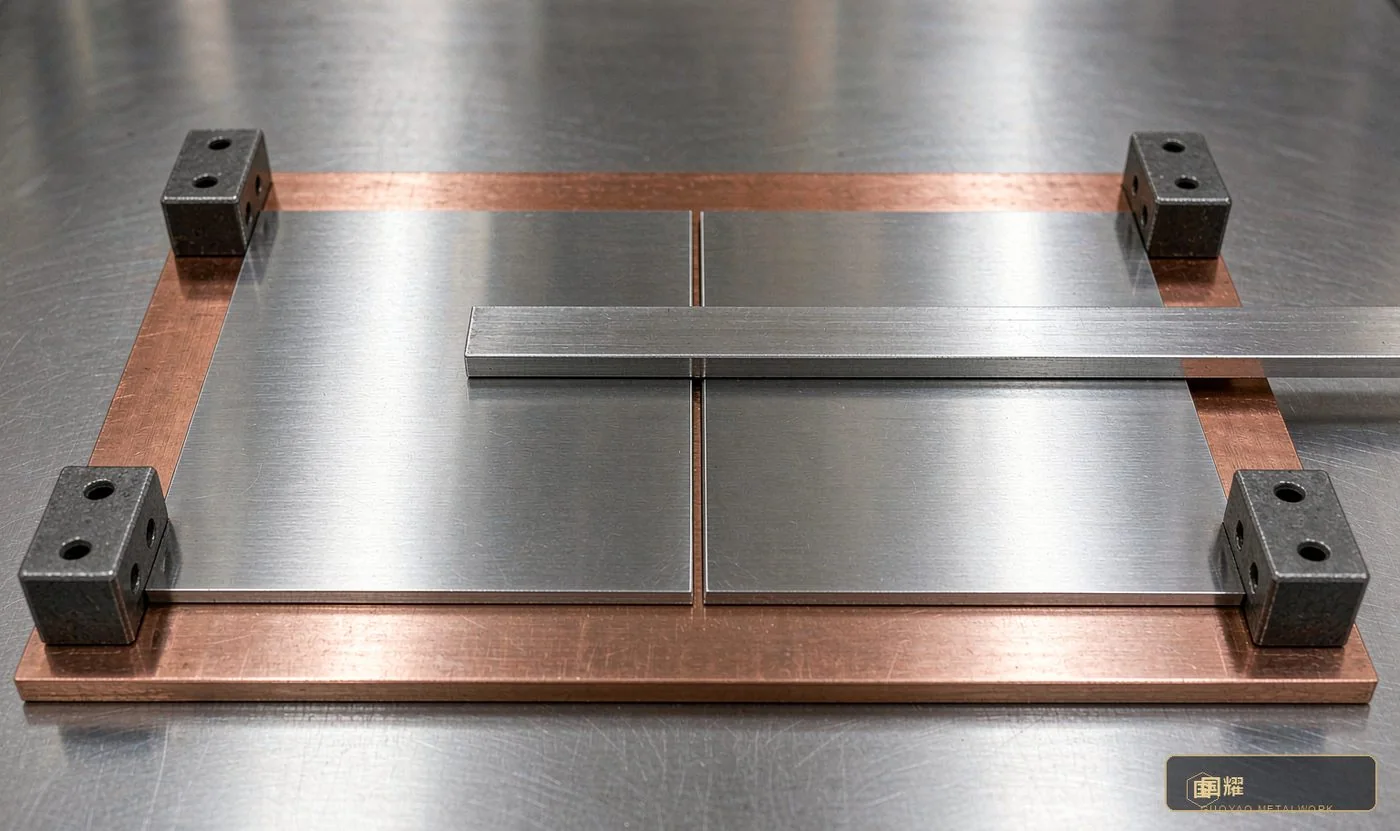
Fig. 2 — Square-butt (I-groove) joint · first choice for sheet
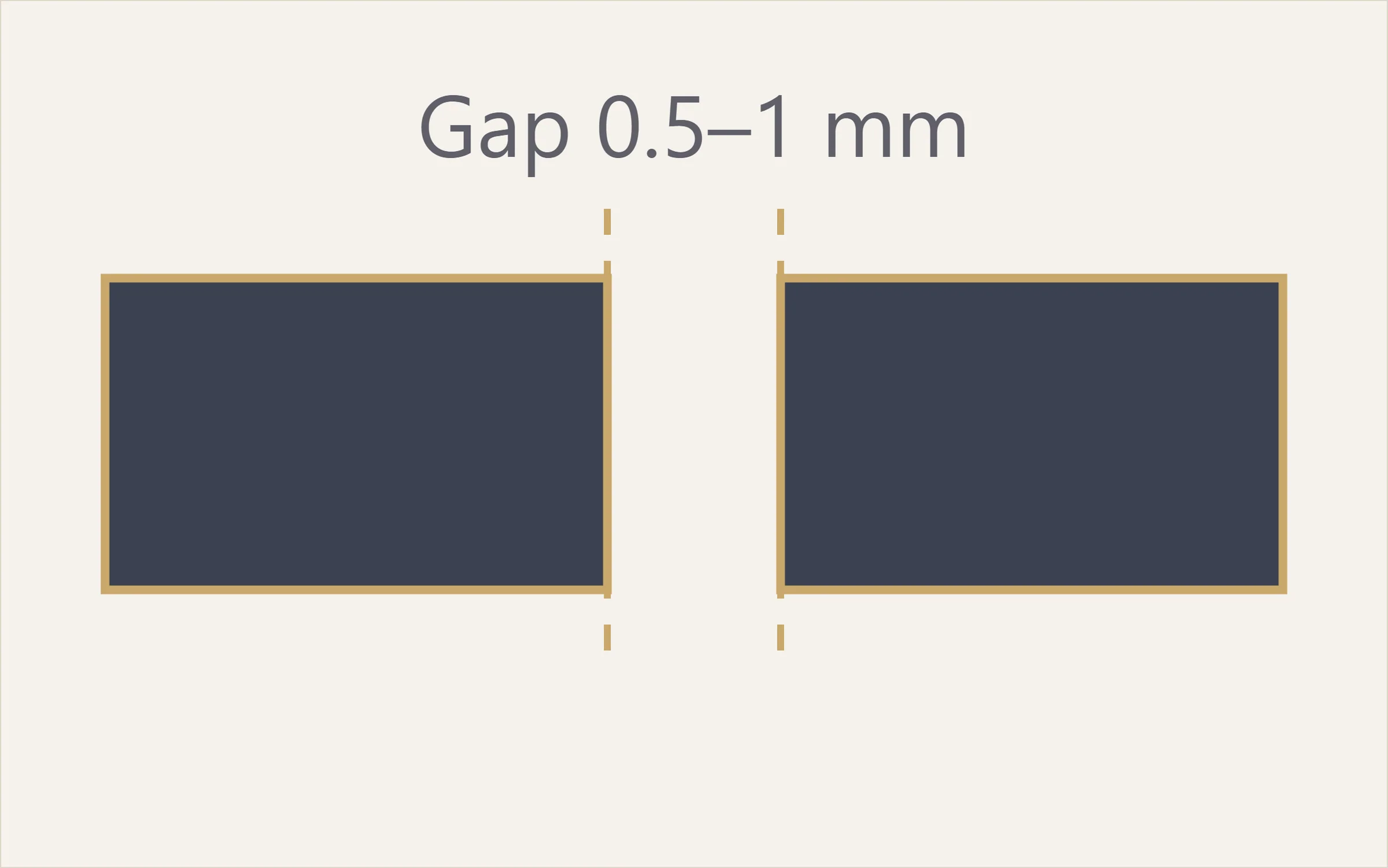
- Thickness range — 0.5–2 mm; laser welding with a square-butt joint is recommended for visible surfaces
- Root gap — 0.5–1.0 mm — the smaller the gap, the less filler and the lower the heat input
- Fit-up points — Square-cut edges, deburred and lightly blunted; levelled on a copper backing with magnetic clamps
- Why it comes first — A smaller groove → less distortion → less grinding: the physical basis of a seamless result
Parameters — Gap 0.5–1.0 mm · root face — · for laser / micro-beam TIG
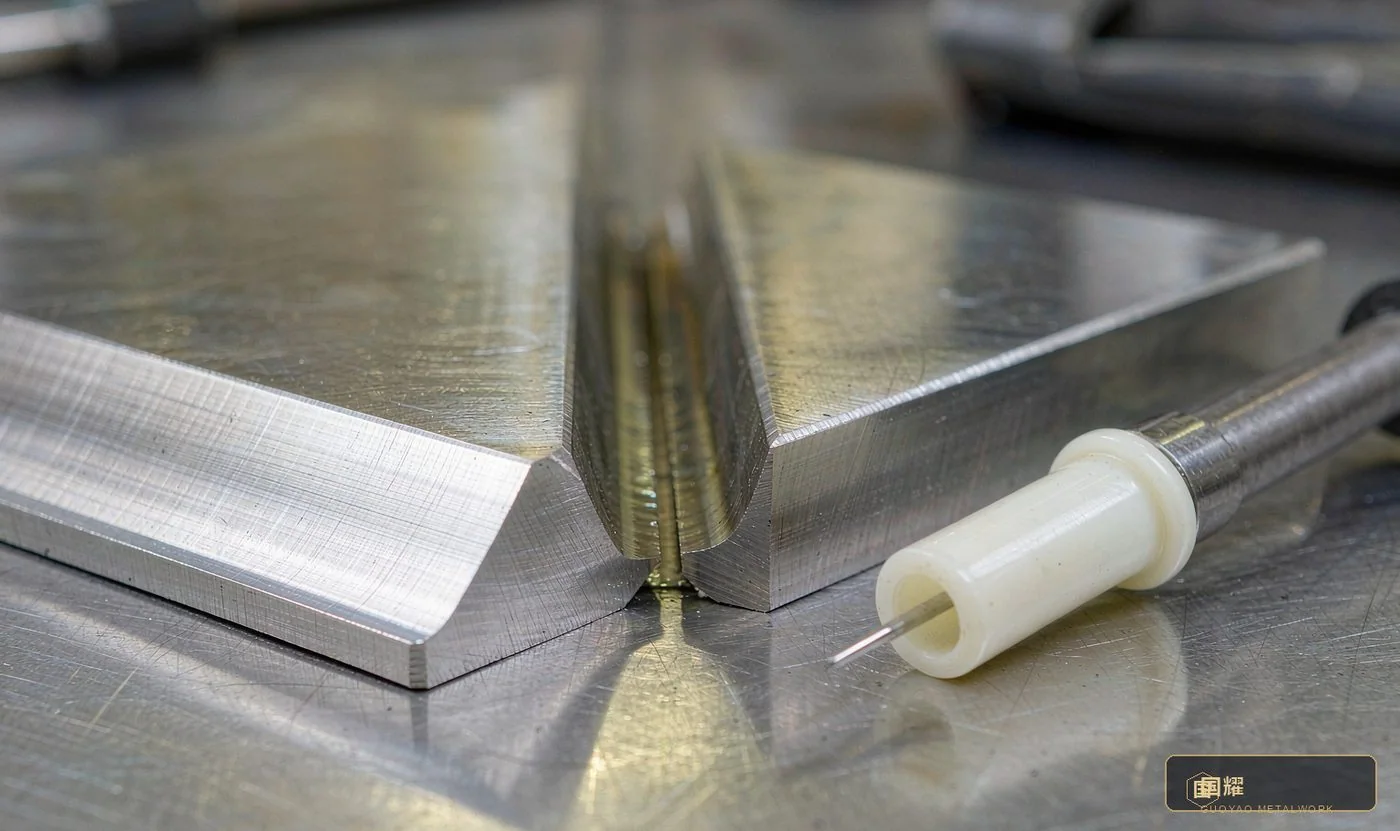
Fig. 3 — V-groove · the workhorse for single-side welding
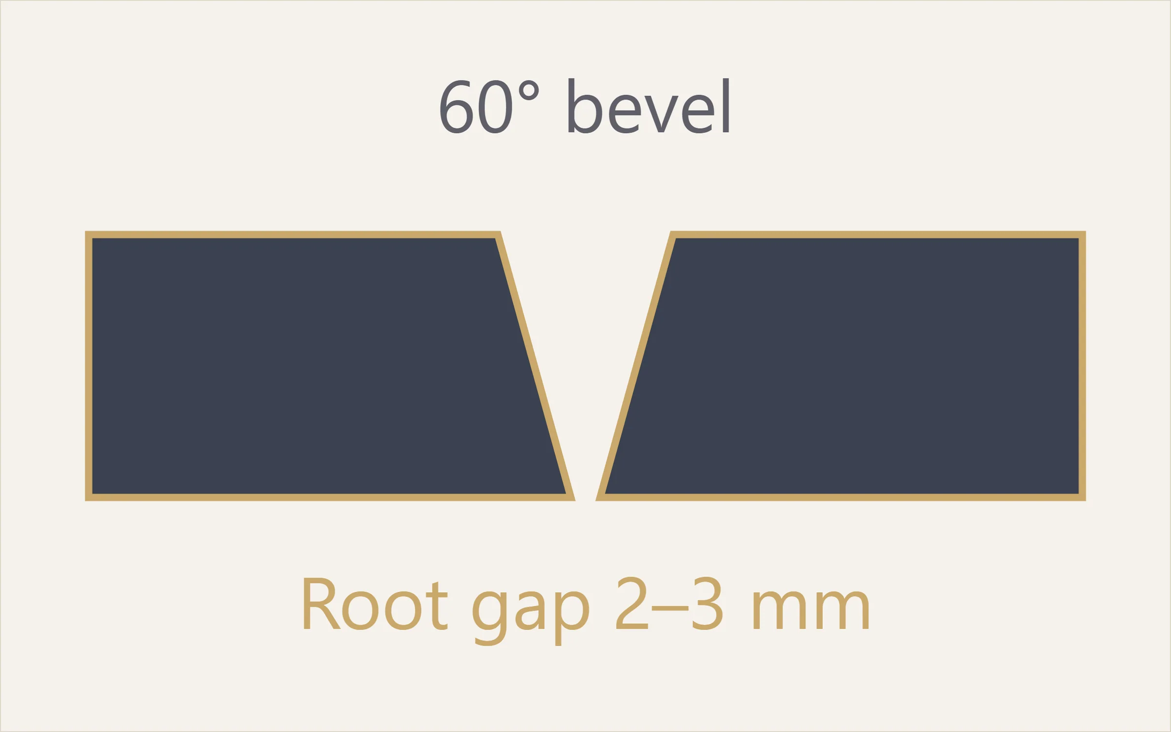
- Thickness range — 3–12 mm (4–8 mm most typical)
- Bevel angle — 55°–65°; machine the bevel faces so the angle stays consistent
- Root gap — 2.0–3.0 mm, root face 1–2 mm
- Welding points — Single-side TIG / MIG; control penetration and back-bead formation on the root pass
Parameters — Thickness 3–12 mm · 55°–65° · gap 2–3 mm · root face 1–2 mm
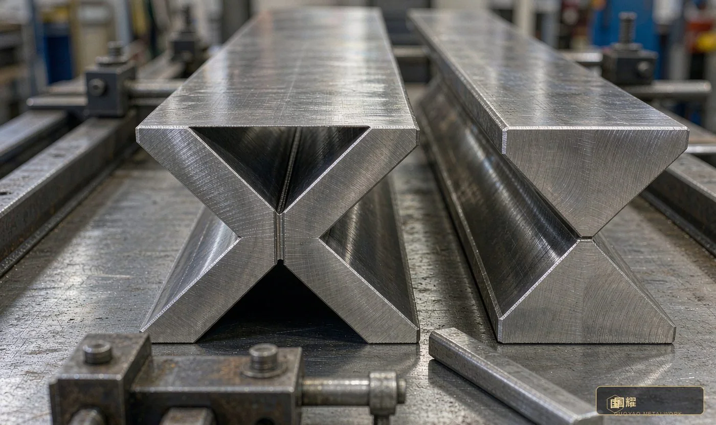
Fig. 4 — X-groove · double-side welding for plate
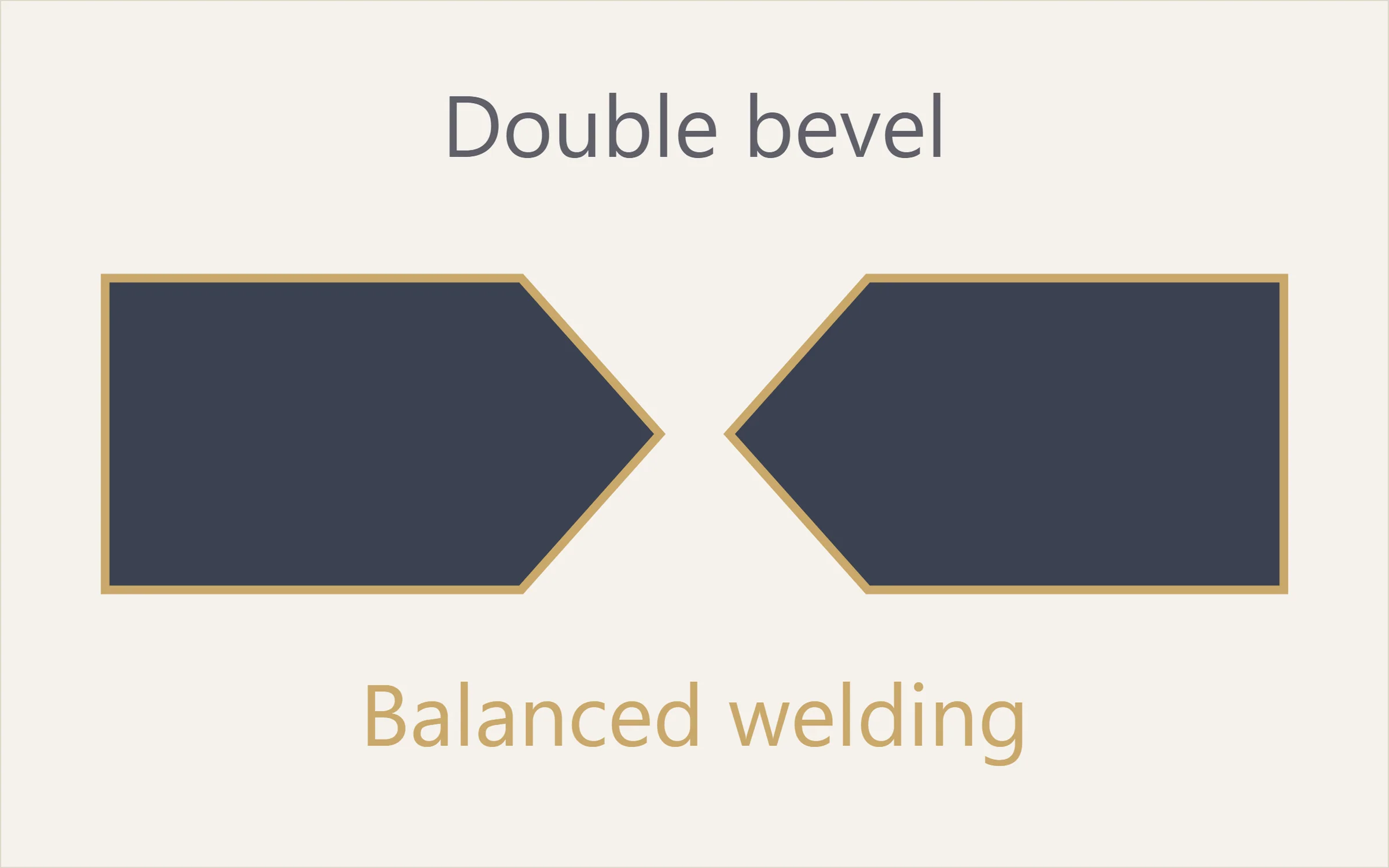
- Thickness range — >12 mm structural parts, welded symmetrically from both sides
- Bevel angle — 50°–60°, with the two bevels symmetrical
- Root gap — 2.0–3.0 mm, root face 2 mm
- Welding points — Multi-pass, alternating between the two sides to cancel angular distortion and residual stress
Parameters — Thickness >12 mm · 50°–60° · double-side multi-pass · interpass ≤150 °C
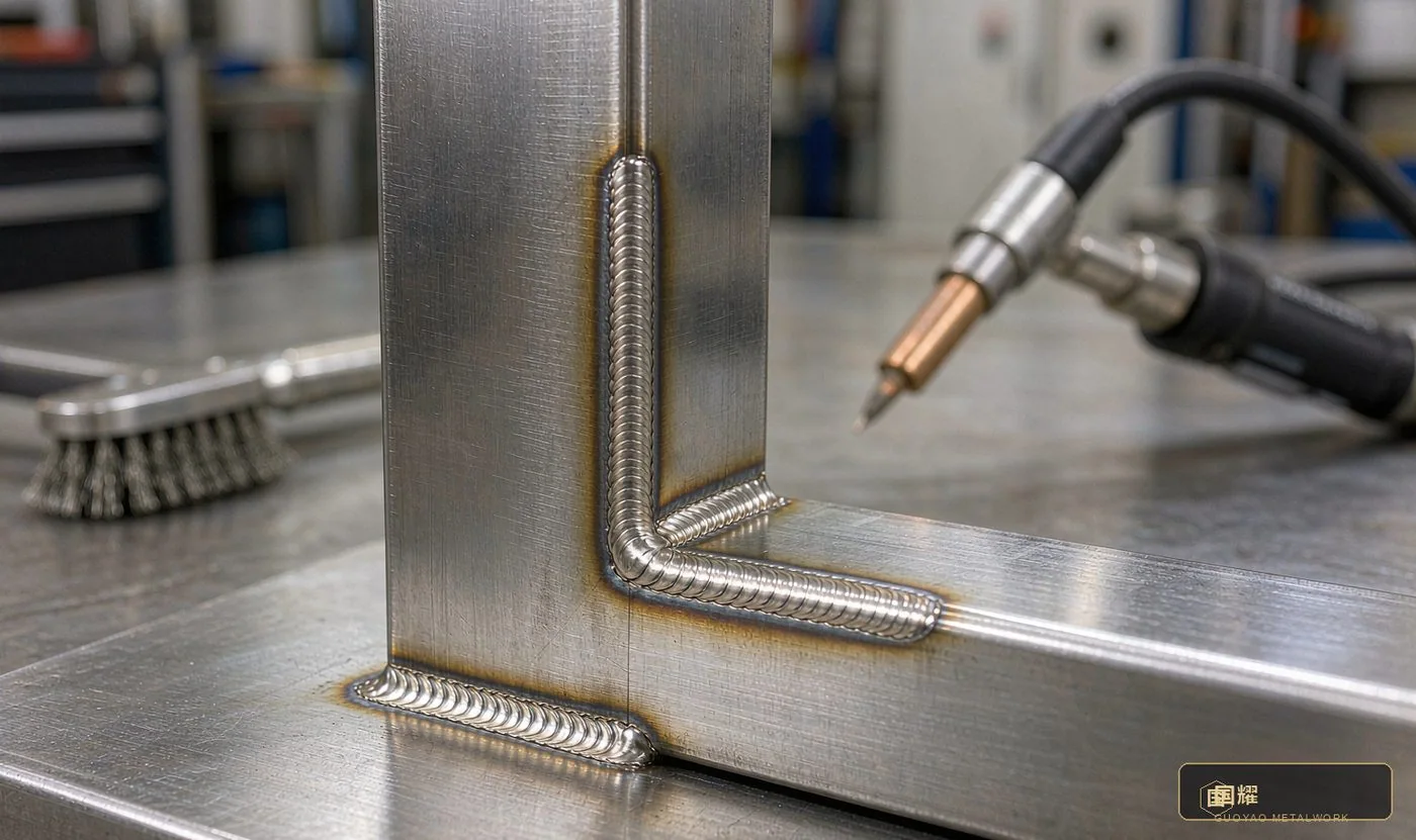
Fig. 5 — T-joint · frames and skeletons
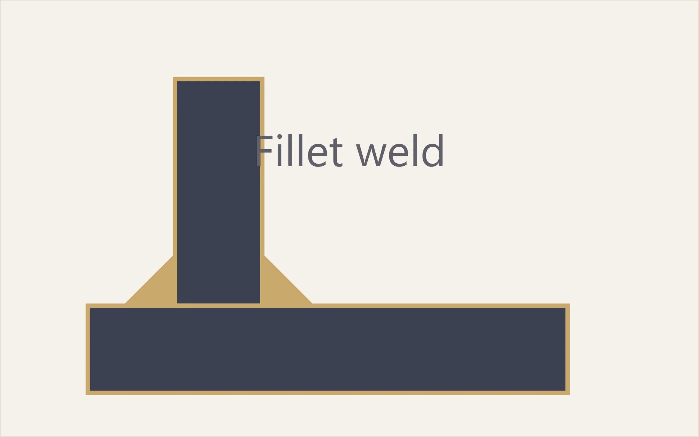
- Typical locations — Skeletons, door surrounds, frames, stiffener connections
- Weld requirement — Full fillet weld, free of cracks and lack of fusion, meeting strength requirements
- Grade split — Concealed faces: deslag and rust-protect (carbon steel) or pickle and passivate (stainless); visible faces: grind level
- Hand-feel standard — Handrail-type beads in residences must be continuous, with no lumps and a smooth transition
Parameters — Structural welds Grade C · visible faces ground to Grade A/B · leg size 1–1.2 × thickness
- 0.5 – 2mm — Recommended groove: I-groove / flanged edge · Bevel angle: — · Root gap: 0.5 – 1.0mm · Root face: — · Process: Laser / micro-beam TIG
- 2 – 4mm — Recommended groove: I-groove or shallow V · Bevel angle: 30° – 45° · Root gap: 1.0 – 2.0mm · Root face: 0 – 1mm · Process: TIG
- 4 – 8mm — Recommended groove: V-groove · Bevel angle: 55° – 65° · Root gap: 2.0 – 3.0mm · Root face: 1 – 2mm · Process: TIG / MIG
- 8 – 12mm — Recommended groove: V / X-groove · Bevel angle: 55° – 60° · Root gap: 2.0 – 3.0mm · Root face: 1.5 – 2mm · Process: Multi-pass MIG / TIG
- >12mm — Recommended groove: X / U-groove · Bevel angle: 50° – 60° · Root gap: 2.0 – 3.0mm · Root face: 2mm · Process: Multi-pass
Note for high-end projects: on visible surfaces, use laser welding with square-butt joints, because a smaller groove means less filler, lower heat input, less distortion and less grinding — the physical basis of a seamless result.
6. Distortion Control and Welding Sequence
Once distortion occurs, it can never be corrected by grinding later
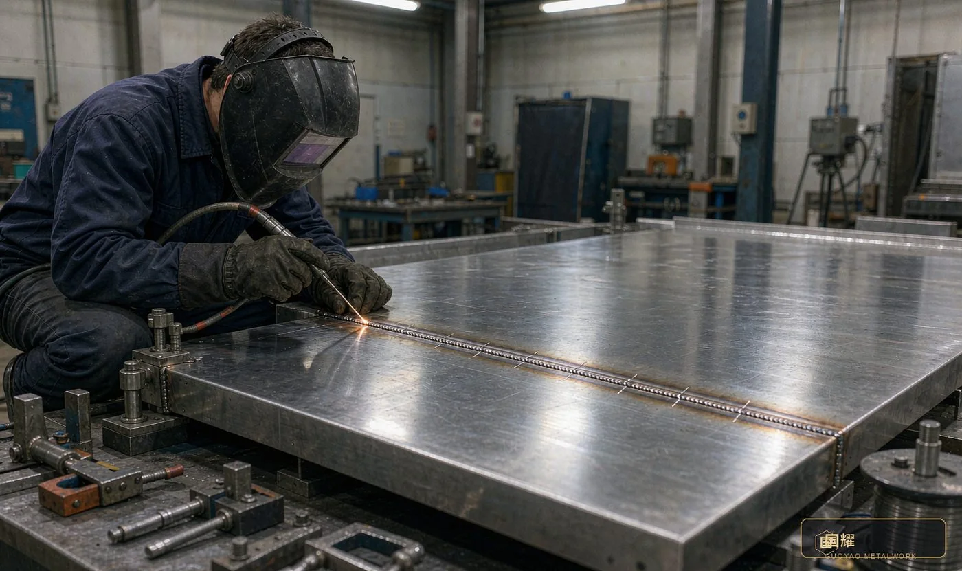
Fig. 6 — Back-step welding · spreading the heat input
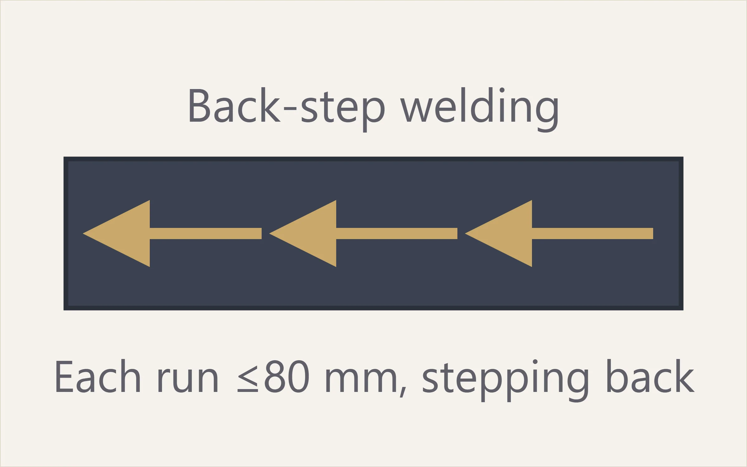
- Run length — Each run ≤80 mm, welded backwards run by run
- Purpose — Prevent heat from building up continuously along the seam and control longitudinal shrinkage
- Supporting measures — Low current, fast travel + copper backing for forced heat sinking
- Suitable for — Large-panel joints and long straight visible seams
Parameters — Run length ≤80 mm · interpass ≤150 °C · control longitudinal shrinkage
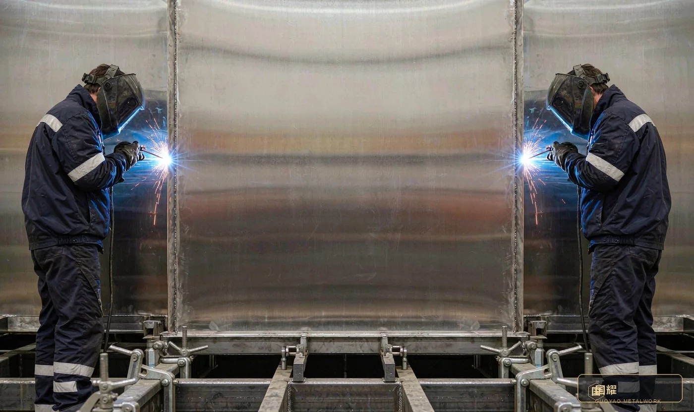
Fig. 7 — Balanced welding · cancelling stress
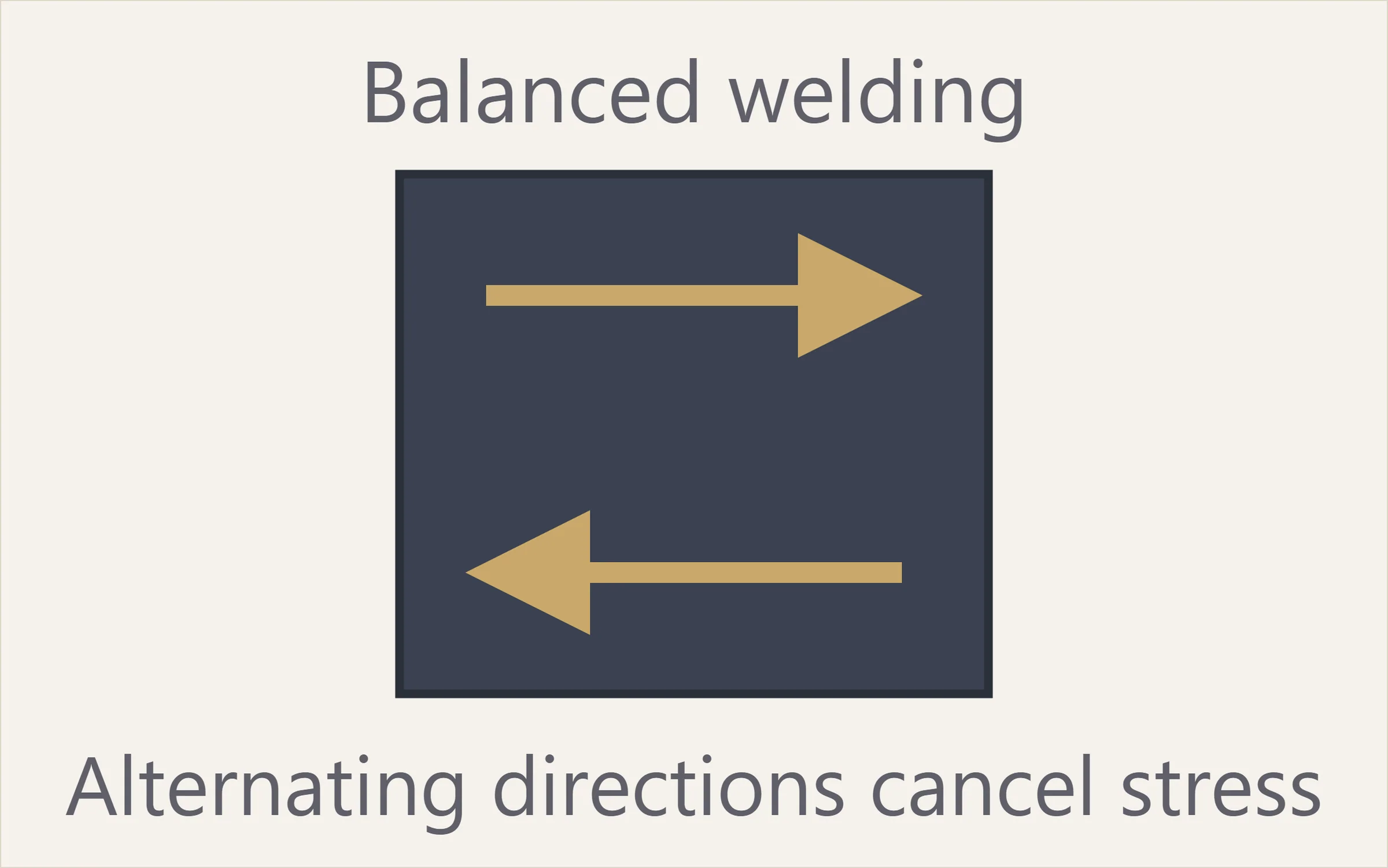
- Method — Both sides / two welders in symmetry, welding in alternating directions
- Purpose — Heat input balanced on both sides so residual stresses cancel each other
- Suitable for — Symmetrical sections and large double-bevel (X) panels
- Caution — Keep the parameters identical on both sides and control interpass temperature in step
Parameters — Two welders, symmetrical · alternating direction · identical parameters
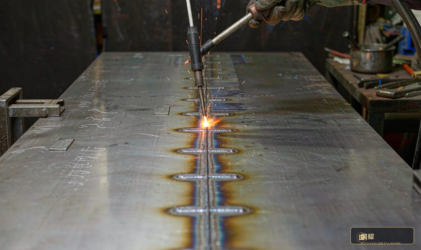
Fig. 8 — Skip welding · first choice for long seams
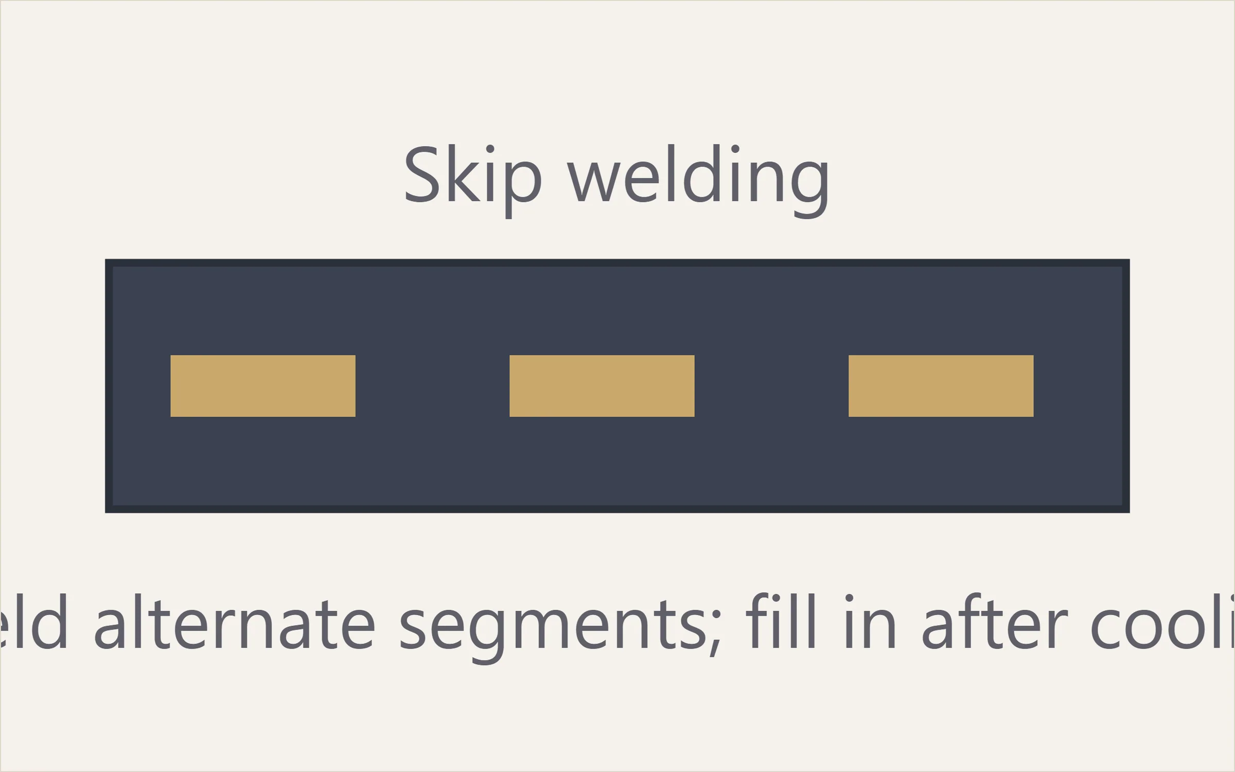
- Method — Weld alternate segments first, then fill in the middle segments after cooling
- Purpose — Spreads heat and prevents localised overheating
- Suitable for — Very long seams and sheet structures prone to distortion
- Caution — Grind the transitions at the tie-in points to avoid steps
Parameters — Alternating segments · fill in after cooling · first choice for long seams
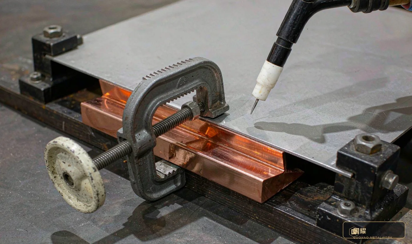
Fig. 9 — Copper backing + jigs · forced heat sinking and rigid restraint
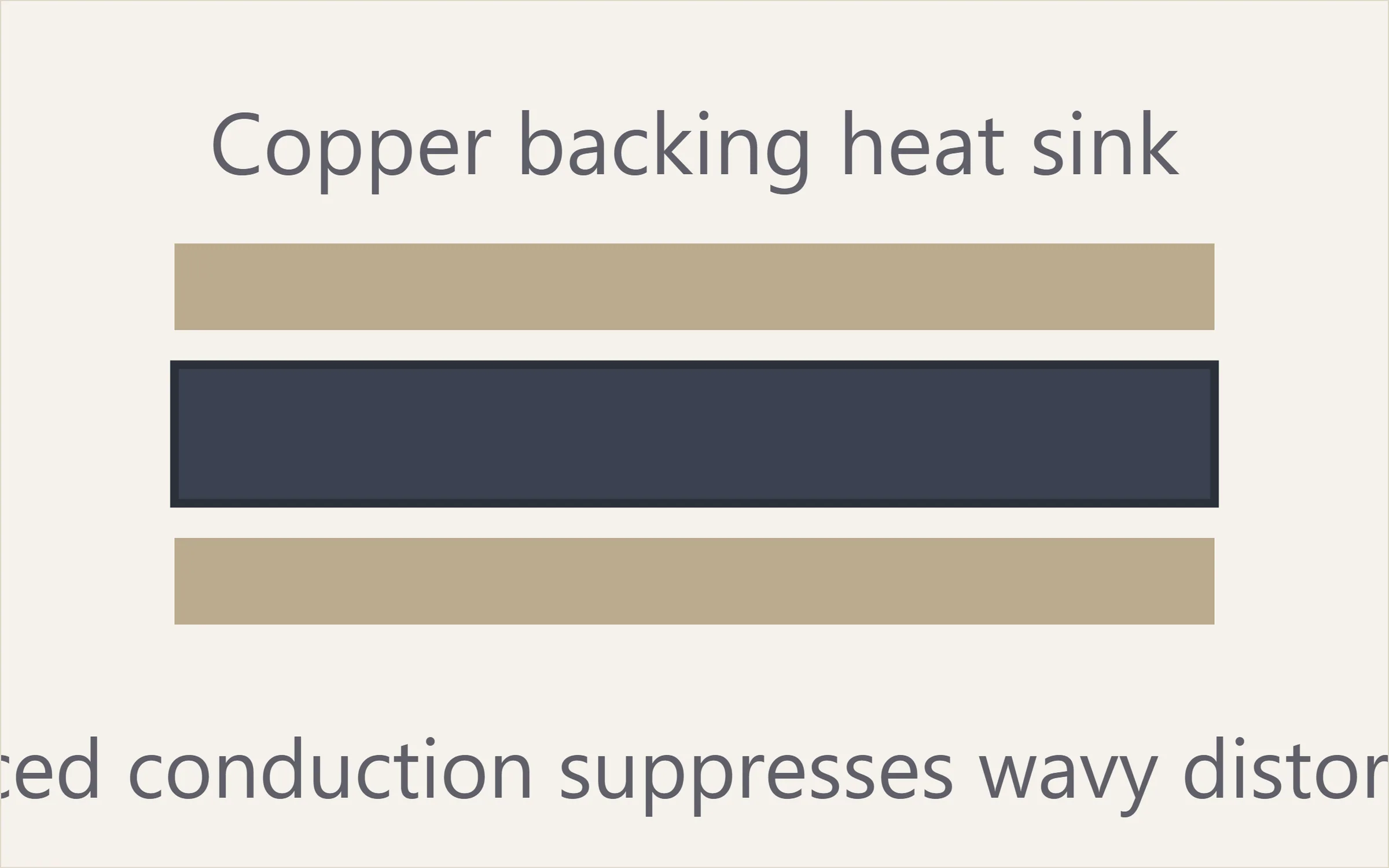
- Heat-sink principle — Copper or aluminium backing bars and heat-sink plates bear on the back of the weld to draw heat away fast
- Rigid restraint — Hold with fit-up jigs, C-clamps and location blocks; remove only after cooling
- What it suppresses — Wavy distortion and collapse — the two great hazards of sheet welding
- Use them together — Works best combined with back-step welding and low current, fast travel
Parameters — Copper heat sinking + rigid restraint · cool before releasing the jig
Six Ways to Control Distortion
① Control the heat input
Low current, fast travel, narrow bead. Laser welding needs only 1/5 to 1/3 of the heat input of TIG and is the first choice for sheet.
② Spread the heat source
Back-step, skip and balanced welding avoid localised heat build-up.
③ Force the heat away
Copper and aluminium backing bars and heat-sink plates bear on the back of the seam and draw heat away quickly.
④ Rigid restraint
Fix with fit-up jigs, C-clamps and location blocks; remove only after cooling.
⑤ Pre-set counterset
Tilt the parts 1–3 mm the opposite way during fit-up to offset post-weld shrinkage.
⑥ Control the interpass temperature
Keep interpass temperature ≤150 °C on multi-pass work, with air or damp-cloth cooling if necessary.
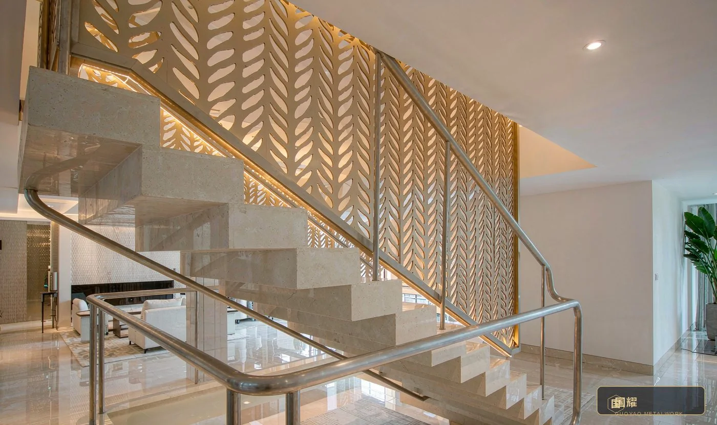
Fig. 10 — Metal screens and stair balustrades in luxury residences
Large metalwork must be welded and straightened in the factory, leaving only assembly and closure on site — once distortion occurs it can never be corrected by grinding later.
- Typical locations — Stair handrails, screens, wine cellars, lift surrounds, fireplaces, furniture hardware
- Core needs — Safety, rounded corners, impact resistance, a warm hand feel, quiet operation, durability
- Process points — Round every exposed edge R2–R5; handrail beads must feel continuous with no lumps
- Straightening requirement — Level and straighten after welding; flatness deviation under a 2 m straightedge ≤1 mm
Target — Factory prefabrication ratio ≥70% · on-site assembly and closure only · Grade B or better, smooth welds
7. Post-Weld Treatment and Surface Finishing
Welding only produces a semi-finished part — surface treatment decides how it finally looks
Grinding and Polishing Grit Reference
- Brushed (fine grain) — Coarse grind: 80–120 grit · Medium grind: 180–240 grit · Fine grind: 320 grit · Polish / brush: Brushing wheel / scuff pad · Gloss reference: Matt, with a uniform grain
- Brushed (snowflake) — Coarse grind: 120 grit · Medium grind: 240 grit · Fine grind: 400 grit · Polish / brush: Nylon wheel + snowflake belt · Gloss reference: Short snowflake pattern with a soft reflection
- Mirror 8K — Coarse grind: 120 grit · Medium grind: 320 → 600 grit · Fine grind: 800 → 1500 grit · Polish / brush: Polishing compound + wool wheel (coarse → fine) · Gloss reference: Ra ≤0.05 μm, no haze
- Matt sandblast — Coarse grind: 240 grit · Medium grind: — · Fine grind: — · Polish / brush: Glass bead / corundum blasting · Gloss reference: Even matt texture, no bright patches
Critical sequence: Welding → deslag → coarse grind → medium grind → fine grind → polish / brush → PVD colour coating → anti-fingerprint spray. The colour coating must come after all grinding and polishing; otherwise the coating will be damaged and the heat will discolour and blister it.
Choosing a Surface Finish
PVD vacuum coating
Titanium gold, black titanium, champagne gold, rose gold, antique bronze, gunmetal grey. The film is hard, wear-resistant and colour-stable — the mainstream choice for high-end projects.
Electroplating / electroless plating
Common on brass. Deposition is even, but environmental restrictions are extensive and adhesion to the base metal must be tested.
Aged / antique finish
Brass is oxidised and brushed to build bronze depth; once aged, the weld blends naturally into the base metal.
Anti-fingerprint (AFP)
A nano coating that markedly reduces fingerprint marks — essential for luxury retail display cases and door handles.
Etching / perforation
Chemical etching creates the pattern; welds must avoid the patterned areas or the pattern will be spoiled.
Anti-soiling, self-cleaning coating
Optional for high-contact areas such as hotel lobbies and revolving doors, reducing long-term maintenance cost.
8. What Matters in Each of the Three Applications
The same processes, but different priorities
🛍 Luxury retail
Typical locations: Shopfronts, display cases, cash counters, skirtings, edge trims, window frames.
Core needs: Seamless, fingerprint-free, no waviness under light, extremely narrow joints (≤0.5 mm).
Recommended approach: Laser welding + square-butt joints + fine polishing + PVD colour coating + anti-fingerprint coating. Welds inside display cases must be completely concealed so that reflected light cannot reveal the bead.
🏛 Luxury residences
Typical locations: Stair handrails, screens, wine cellars, lift surrounds, fireplaces, furniture hardware.
Core needs: Safety, rounded corners, impact resistance, a warm hand feel, quiet operation, durability.
Recommended approach: Strong structural welds + smoothly ground visible faces + every exposed edge rounded R2–R5; handrail beads must feel continuous with no lumps.
🏨 Luxury hotels
Typical locations: Lobby screens, art installations, lift lobbies, revolving doors, balustrades, canopies.
Core needs: Distortion control on large panels, fire rating, structural strength, consistent colour, batch-to-batch uniformity.
Recommended approach: Factory prefabrication + on-site assembly + segmented balanced welding, with same-batch material and same-furnace colour coating to guarantee no colour difference over large areas.
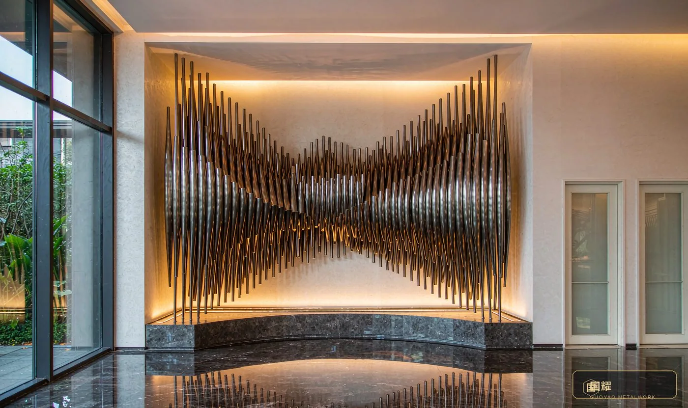
Fig. 11 — Luxury hotel lobby · large-scale metal art installation
Large metal installations are normally broken into factory-prefabricated units assembled on site with concealed connectors, minimising site welding and hot work.
- Typical locations — Lobby screens, art installations, lift lobbies, revolving doors, balustrades, canopies
- Core needs — Distortion control on large panels, fire rating, structural strength, consistent colour, batch uniformity
- Prefabrication strategy — Split into units + segmented balanced welding in the factory + on-site assembly with concealed connectors
- Colour control — Same-batch base metal, same-furnace coating; no difference at 1 m to the naked eye and consistent under light
Target — No colour difference over large areas · zero site welding preferred · joints ≤0.5 mm and even
Priority Comparison Across the Three Applications
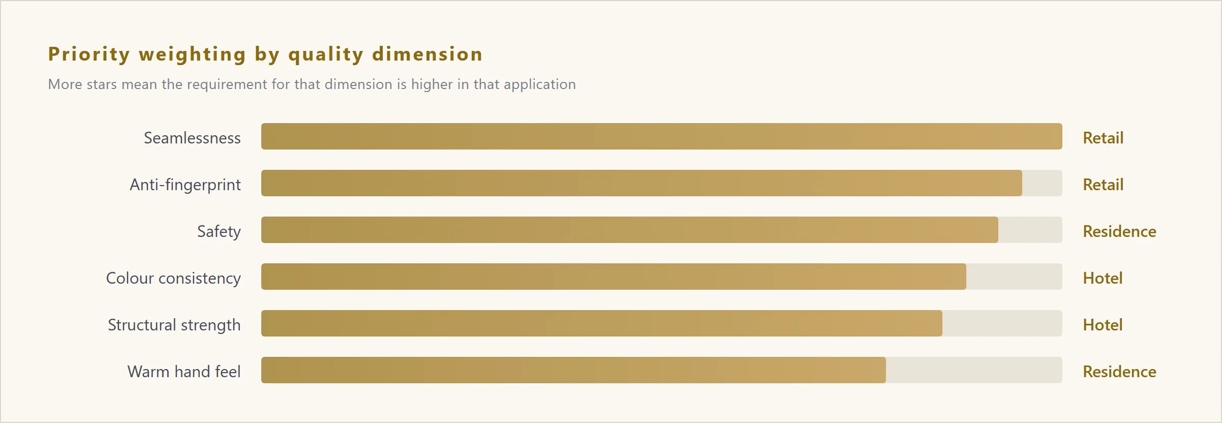
- Seamlessness — relative weighting 100 · highest for retail
- Anti-fingerprint — relative weighting 95 · highest for retail
- Safety — relative weighting 92 · highest for residence
- Colour consistency — relative weighting 88 · highest for hotel
- Structural strength — relative weighting 85 · highest for hotel
- Warm hand feel — relative weighting 78 · highest for residence
9. Common Defects and Prevention
The eight most frequent problems on high-end projects
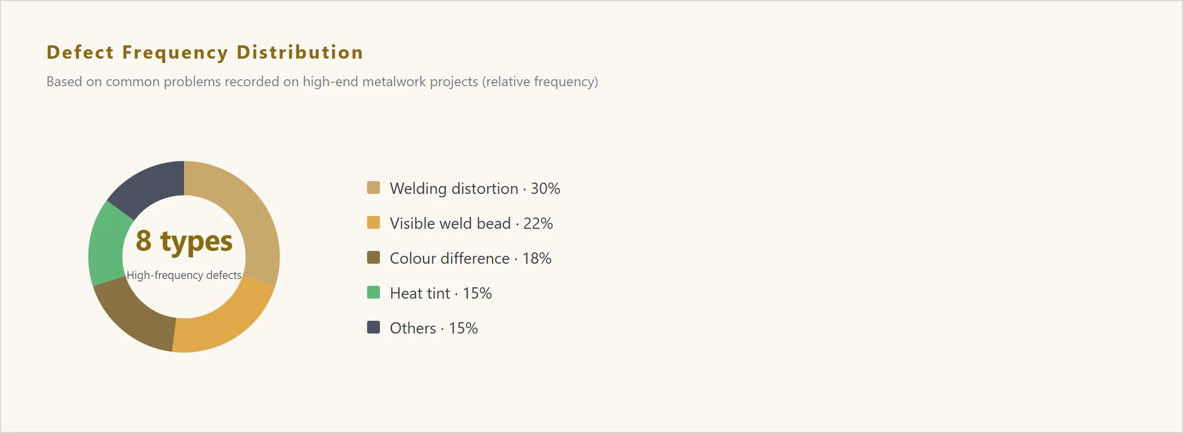
- Welding distortion — 30%
- Visible weld bead — 22%
- Colour difference — 18%
- Heat tint — 15%
- Others — 15%
- Welding distortion — Cause: Excessive heat input, wrong welding sequence, no rigid restraint · Prevention: Low current, fast travel, back-step sequence, copper backing for heat sinking, jig restraint, pre-set counterset · Remedy: Minor cases can be straightened mechanically; severe cases must be scrapped and remade
- Undercut — Cause: Current too high, travel too fast, filler fed too late · Prevention: Reduce current, steady the travel, feed filler promptly · Remedy: Weld up and grind level
- Porosity — Cause: Oil or moisture on the base metal, insufficient argon purity, draught interference · Prevention: Acetone cleaning, argon ≥99.99%, wind screens · Remedy: Gouge out the defect and re-weld
- Lack of fusion — Cause: Current too low, travel too fast, insufficient bevel angle · Prevention: Verify the parameters, open the groove, control travel speed · Remedy: Gouge out and re-weld; re-test by NDT if necessary
- Cracks — Cause: Wrong filler, cooling too fast, high restraint stress · Prevention: Match the filler, preheat and cool slowly, reduce restraint · Remedy: Must be gouged out and re-welded — never hidden by grinding
- Heat tint — Cause: No argon backing, insufficient shielding-gas flow · Prevention: Argon backing, higher flow, shorter arc · Remedy: Remove by pickling and passivation, or grinding
- Colour difference — Cause: Different base-metal batches, different wire, different coating batches · Prevention: Single-batch purchasing, same-furnace coating, keep a reference sample · Remedy: Large-area colour difference cannot be repaired — only replaced
- Rust staining / fingerprints / scratches — Cause: Iron-ion contamination, no anti-fingerprint treatment, inadequate protection during construction · Prevention: Dedicated segregated tools, anti-fingerprint coating, protective film and corner guards · Remedy: Local polishing repair; deep scratches require replacement
Irreversible defects: large-area distortion, colour difference after coating, deep scratches on mirror surfaces, burn-through and collapse. Once any of these four occurs, it cannot be repaired afterwards, the whole part has to be replaced. The focus of quality control on high-end projects must therefore move upstream to sampling and first-article approval.
10. Acceptance Criteria and Safety Rules
Visible standards + invisible red lines
Weld Quality Acceptance
- Cracks — Acceptance criterion: Not permitted · Instrument: Visual + 10× magnifier / dye penetrant testing
- Porosity — Acceptance criterion: Not permitted on Grade A; ≤0.5 mm each on Grade B, ≤3 per metre · Instrument: Visual + magnifier
- Undercut — Acceptance criterion: Not permitted on Grade A; depth ≤0.3 mm on Grade B · Instrument: Visual + weld gauge
- Reinforcement — Acceptance criterion: Grade A 0 (flush with the base metal); Grade B ≤0.5 mm · Instrument: Weld gauge / feeler gauge
- Weld overlap, spatter — Acceptance criterion: Not permitted · Instrument: Visual
- Heat tint — Acceptance criterion: Not permitted on visible surfaces · Instrument: Visual
Installation and Appearance Acceptance
- Surface flatness — Permitted deviation: ≤1mm / 2m · Method: 2 m straightedge + feeler gauge
- Verticality of the face — Permitted deviation: ≤1.5mm · Method: 2 m verticality gauge
- Squareness of internal / external corners — Permitted deviation: ≤1.5mm · Method: Square gauge
- Joint width (Grade A) — Permitted deviation: ≤0.5 mm, and uniform · Method: Feeler gauge + visual
- Straightness of joints — Permitted deviation: ≤1mm / 2m · Method: String line + steel rule
- Colour difference — Permitted deviation: No visible difference at 1 m; consistent under light · Method: Comparison with the sample + raking light
Safety Rules (essential reading for site welding)
- Obtain a hot-work permit; provide extinguishers, spark buckets and fire blankets
- Assign a dedicated fire watcher, on watch throughout the work and for 30 minutes afterwards
- Clear combustibles within 5 m of the work area; mask finished work and decorative surfaces
- Forced extraction of welding fume; a respirator is mandatory for aluminium, brass and galvanised parts
- Wear a welding helmet, protective gloves, flame-retardant clothing and insulated footwear
- Stand gas cylinders upright and secured, at least 5 m from ignition sources; store oxygen and acetylene separately
- Temporary power with three-stage distribution and two-stage protection; reliable earthing of the welder
- Wear a harness for work at height; scaffold and lift platforms may be used only after inspection approval
- Replace site welding with factory prefabrication wherever possible to cut hot-work time
- Clear welding slag before finishing, and leave only once no smouldering risk remains
Maintenance Points
Routine cleaning
Neutral detergent and a soft cloth. Never use strong acids, strong alkalis or chlorine-based cleaners (bleach, toilet cleaner) — they cause pitting of stainless steel.
Mirror / anti-fingerprint surfaces
Use a dedicated microfibre cloth and wipe in one direction along the grain. Avoid circular rubbing, which leaves haze marks.
Scratch repair
Brushed surfaces can be re-brushed locally along the grain; mirror surfaces can be polished locally; PVD-coated surfaces cannot be repaired and must be returned to the factory for recoating.
The Whole Process in One Line
Printable — post it in the workshop and the project office
Detailing and sampling → factory cutting → fit-up and tacking → laser / TIG welding → post-weld grinding and polishing → surface coating → site installation and closure → acceptance and maintenance
Factory prefabrication first · minimal site welding · sample before production · Grade A welds on visible surfaces